Metallic grain structures

Metallic grain structures and microscopic analysis

Metallic materials are often interpreted in terms of their inner structure – known as the microstructure. Prepared in cooperation with optics and optoelectronics experts Zeiss, this application note explains all you need to know about the structural properties of metal, preparing materials for microstructural analysis and interpreting the results.

Download the full application note

The structural properties of metals

The inner structure of a metal is made up of individual crystalline areas known as ‘grains’. The structure, size and orientation of these grains result from the material composition (alloy) and the way the material is made (e.g. forging, casting or additive manufacturing). The grains are formed from the molten material when it solidifies, interact with one another and with other ingredients, like phases and contaminations. Typically, the grain structure is adapted to the technical application.

Grain size and orientation and other structural characteristics are directly linked to the mechanical and technological properties of these materials. Structural characteristics also depend on subsequent external influences. These influences include:
  • Chemical influences (e.g. corrosion)
  • Chemical and/or physical influences (e.g. heat treatment processes)
  • Mechanical influences (e.g. following the forming processes, such as forging, rolling, bending, etc.)

Microstructure

Metallic grain structures
Fig. 1: Pure copper etched in DIC

Microstructure can only be assessed by microscope (stereo microscope, light microscope using reflected light, digital microscope or scanning and transmission electron microscope). Usually, the size of characteristics observed range from parts of millimeters down to micrometers and even nanometers. Microstructural observations are used for a wide range of investigations, for example, to determine grain sizes, check for defects, target preparation in microelectronics, welds of all kinds and failure analysis.

Macrostructure

Metallic grain structures
Fig. 2: Pure copper macro section part of cast block etched

Macrostructure can be seen with the naked eye, a magnifying glass or stereo microscope. These observations are less common than microstructural investigations. Applications where macrostructure is observed are typically welds, cast parts of some nonferrous metals or deformation and segregation on cast or forged parts. The rough evaluation of coatings or geometries can also be the topic of macrostructural investigations.

Why microscopic analysis?

Once metallographic preparation is complete, the structural properties of a metal can be analyzed under a microscope. It is then possible to draw conclusions regarding the characteristics of the material. For example, microscopic analysis can be used to evaluate characteristics in the metal design and processing stages, as well as cases in which damage has occurred.

Structural elements that can be evaluated using a light or electron microscope include:
  • Grains/crystallites and their grain boundaries
  • Intermetallic phases and precipitates
  • Non-metallic inclusions and phases
The evaluation is based on the following criteria:
  • Type and form
  • Size and number
  • Distribution and orientation


Based on all of this information, it is then possible to create a comprehensive description of the microstructure and draw conclusions regarding its potential characteristics.

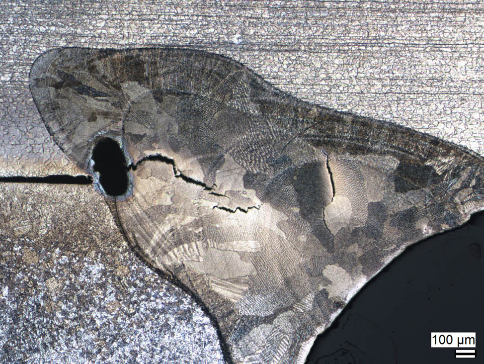
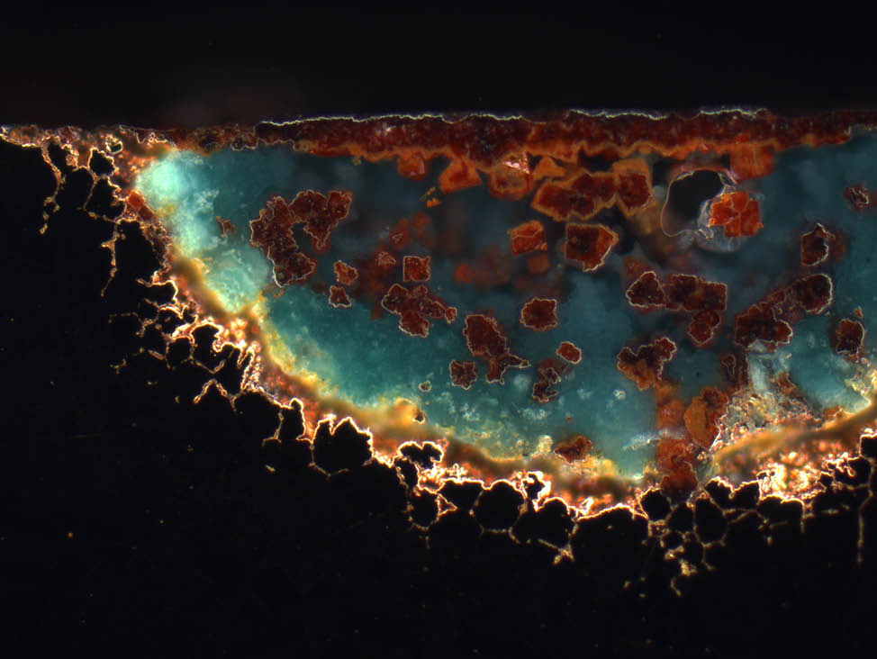
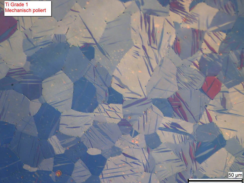
Understanding alloys

The materials used in practical applications today are a mixture of various chemical elements, often also referred to as ‘alloys’. Steel and cast iron, for example, are essentially alloys based on iron (Fe) with carbon (C) alloying additions, which are responsible for the hardness of the ferrous material. Microstructural analysis enables us to draw conclusions regarding the properties of the alloy, including its strength, hardness and ductility

Metallic grain structures
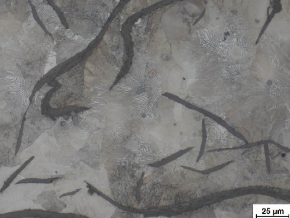
Fig. 3: Pearlitic cast iron with lamellar graphite, etched with Nital. The carbon is primarily present as graphite in a lamellar form, which results in reduced strength. The pearlitic matrix itself exhibits a sufficiently high degree of hardness.
Image taken with ZEISS Axio Imager, 50x objective, brightfield illumination

Metallic grain structures
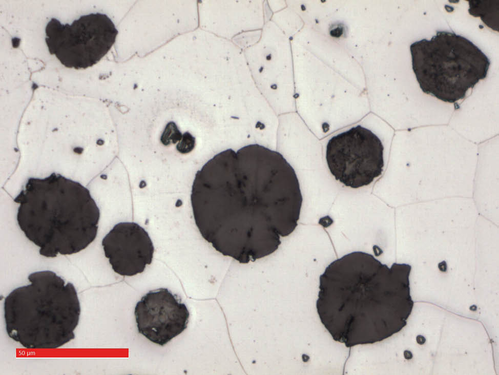
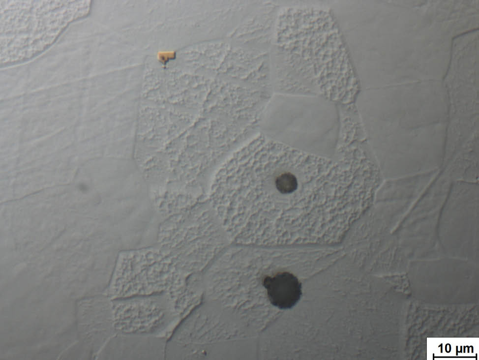
Fig. 4: Ferritic cast iron with spheroidal graphite, etched with Nital. The carbon is primarily present as graphite in a spherical form. The spherical form results in improved strength in comparison to lamellar cast iron, but the hardness of the material is lower due to the lack of cementite in the purely ferritic matrix.
Image taken with ZEISS Smartzoom 5, at approx. 500x magnification

Metallic grain structures
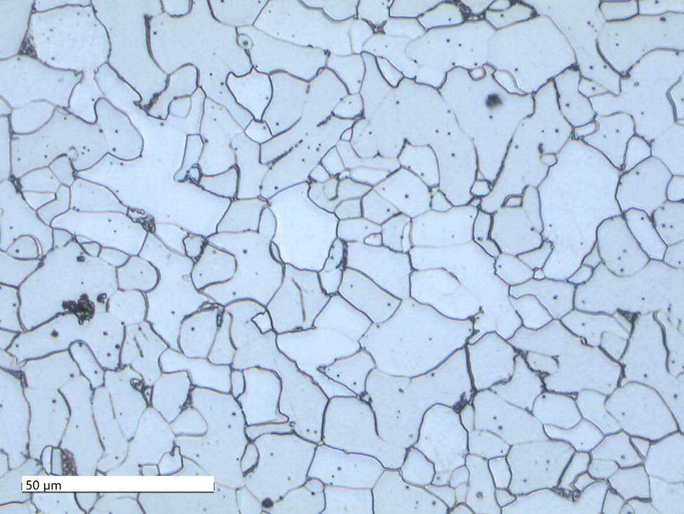
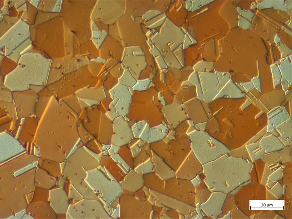
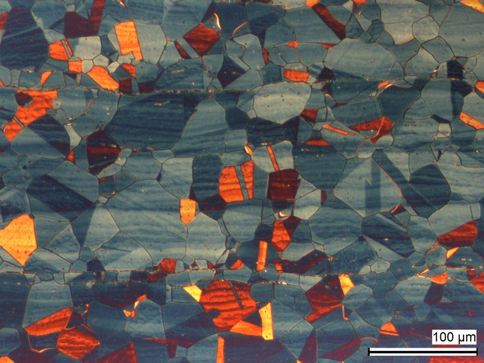
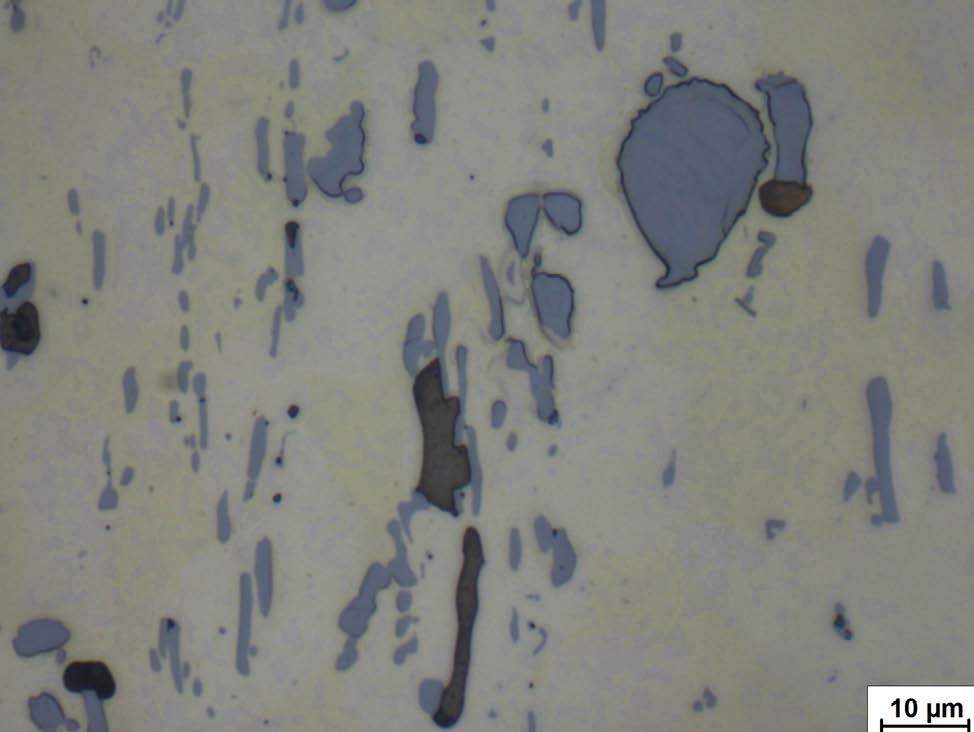
Fig. 5: Ferritic steel with approx. 0.1 % C, etched with Nital. The carbon is primarily present in the form of cementite and as a low proportion of pearlite between the ferritic grains. The matrix, which is therefore nearly purely ferritic, has a low degree of hardness but very good ductility.
Image taken with ZEISS Smartzoom 5 at approx. 500x magnification, coaxial illumination with low proportion of ring light

Metallic grain structures
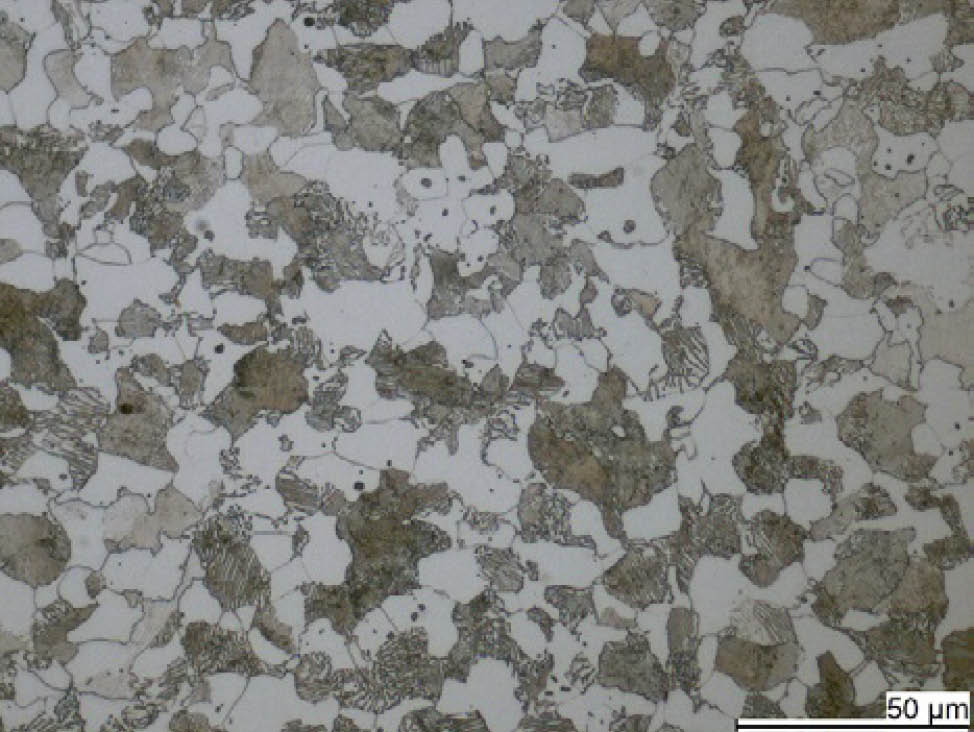
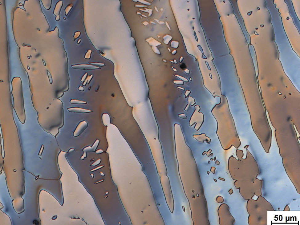
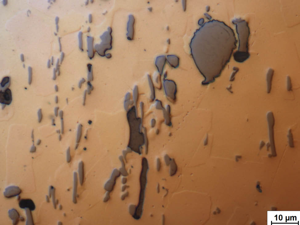
Fig. 6: Ferritic-pearlitic steel with approx. 0.2 % C, etched with Nital. The carbon is primarily present as a cementite lamellar in a harder proportion of pearlite adjacent to the ferritic grains. This causes the cementite to appear streaky. The pearlitic grains reflect less light than the ferritic grains and thus appear darker. A matrix of this type has higher hardness, but lower ductility.
Image taken with ZEISS Axiolab, 50x objective, brightfield illumination

Metallographic preparation of metal for microstructural analysis

To ensure the correct representation of the structural properties of a metal, the sample must be prepared correctly. The steps below give a general description of the process, but the metallographic preparation method should be tailored to the material.

Step 1: Cutting workpieces for microstructural analysis

A wet abrasive cutting process is used to take a representative sample from the workpiece. The cutting process should be chosen to ensure that the sample is not subjected to any damage that will modify its structure, and should be tailored to the material and application.

Metallic grain structures
Fig. 7: A wet abrasive cutting machine with clamped gear wheel, being used to take a sample from a gear tooth section. Typically, the section will be induction- or case-hardened. The sample will be used to examine the section’s structure and hardness.

Find out more

Step 2: Mounting samples for microstructural analysis

A mounting process is used to fix the cut pieces so they can be handled more easily and to standardize their dimensions. A range of hot and cold mounting techniques and resins can be used, although epoxy or acrylic resin are typical.
  • Cold mounting: up to approx. 100 °C, at atmospheric pressure or in a vacuum
  • Hot mounting: at max. 350 bar and 180 °C

Metallic grain structures

Fig. 8: A variety of embedded samples of varying shapes. Mounting a sample with synthetic resin ensures a good preparation outcome and improves efficiency in the rest of the process.

Find out more

Step 3: Grinding and polishing samples for microstructural analysis

The grinding and polishing process is the most important step when preparing a sample for examination under microscope. During this process, the macroscopic roughness of the cut surface is reduced to a reflective surface.

If the intention is only to make the macrostructure visible – typically for examination using a stereo microscope or magnifying glass – a few coarse grinding steps and contrasting with acidic or alkaline solutions is sufficient. (These samples are often prepared unmounted to save time.)

To make the microscopic elements of the structure visible under a reflected-light microscope, a mirror finish is required. The grinding and polishing process flow for a mirror is as follows:
  • Initial coarse grinding is performed on the surface.
  • The surface is gently polished with fine to very fine abrasives until nearly all damaged areas are removed, typically using diamond, aluminum oxide or colloidal silicon dioxide on appropriate polishing cloths and discs.
  • The surface is checked using the differential interference contrast (DIC) – a contrast option in reflected light microscopes – to ensure the surface quality is high enough to continue with etching. If deformation can still be seen in DIC, further polishing steps are required.
  • The surface is etched to enhance contrasts that are invisible or only visible to a limited extent under brightfield conditions. Typically, only weak acids are used.
  • Low concentrated etchants containing 1-3% nitric acid in ethanol (Nital) are very often used for low-alloyed and medium-alloyed carbon steels or cast iron.
  • Corrosion-resistant steel requires special etching processes, such as color etching .


Metallic grain structures
Fig. 9: Welding seam ground on two levels of SiC foil, followed by macro etching with 5 % aqueous nitric acid.
Image taken with ZEISS Stemi 508 stereo microscope at 15x magnification

Metallic grain structures
Fig. 10: Ferritic steel with titanium carbide and oxide inclusions following mechanical preparation to 1 μm diamond. Fine traces of deformations can still be observed in the differential interference contrast image. The sample has not been etched.
Image taken with ZEISS Axio Imager, DIC, 100x objective

Metallic grain structures
Fig. 11: Corrosion-resistant austenitic steel after final polishing with OP-S and subsequent Lichtenegger and Bloech color etching. Austenite grains with twins and ghost lines in the direction of deformation become visible.
Image taken with ZEISS Axio Imager, brightfield illumination, 20x objective

Metallic grain structures
Fig. 12: Corrosion-resistant austenitic-ferritic steel (Duplex) following electrolytic etching in 20 % sodium hydroxide solution. The austenite grains (light brown) are embedded in the bluish-brown ferritic matrix.
Image taken with ZEISS Axiolab, DIC, 20x objective


Find out more

Analysis characterization of metal grain structures

Once metallographic preparation is complete, metal grain structures can be visibly analyzed under a light microscope. This typically occurs at magnifications of 25x to 1000x, which corresponds to the limits of traditional light microscopy. Lattice defects, structures and elements at the sub-microscopic level (less than 1 μm) and down to the atomic level are assessed using electron microscopes. 

Table 1: Examples of applying contrasting techniques for examining metallic structures

Contrasting techniques

There are a number of contrasting techniques that can be used to assess the structural properties of metal. Your choice of contrasting technique depends on a number of factors, including what material you are working with and what characteristics you need to analyze. What contrasting techniques are available and when should they be used?

Brightfield
Brightfield is a standard technique for all types of material analyses. Fissures and pores, non-metal phases and oxidation products are first observed in an unetched condition, as they typically exhibit different reflective behavior than the base metal. The location of fissures and pores in relation to other structural characteristics, on the other hand, can typically only be evaluated if appropriate chemical etching has been carried out.

Metallic grain structures
Fig. 13: Laser welding seam on high-alloy steels with fissures and pores following electrolytic etching. These are also visible in the unetched condition, but the inter-crystalline course of the fissures can only be evaluated after etching has been completed.
Image taken with ZEISS Axio Imager, brightfield illumination, 5x objective

Darkfield

The darkfield technique is mainly used in the microscopy of non-metal materials. However, it offers several advantages when characterizing metals, as well as when evaluating colored structures such as layers of lacquer or plastic coatings on metal substrates. It can also be used to evaluate corrosion products. Darkfield microscopy can be used to show very fine scratches on polished samples as a method of examining grinding quality.

Metallic grain structures
Fig. 14: Corroded area on a brass pipe, unetched. Reflective areas appear dark (metal substrate) under the darkfield illumination, while the corrosion products can be observed in their own color.
Image taken with ZEISS Axio Imager, darkfield illumination, 20x objective

DIC (differential interference contrast)

DIC is a useful tool for analyzing very fine deformations that may still be present in the surface after polishing. It can also be used to distinguish hard and soft structural elements, because hard phases are removed to a lesser extent than softer ones during the final polishing process and, therefore, ‘protrude’ from the surface. This minimal difference is not typically visible under a brightfield microscope, but can been seen in DIC. As a result, DIC can be used to make a qualitative distinction between the hardness of different phases.

With DIC, it is also possible to make grain structures, such as grain boundaries, visible in an unetched condition. This enables you to evaluate the structure prior to etching, removing the need to use chemicals on difficult-to-etch materials, such as corrosion-resistant metals. However, a perfect final polish is required in this case.

Metallic grain structures
Fig. 15: Copper alloy after final polishing. Due to their reflectivity, the various phases appear to have different colors under a brightfield microscope.
Image taken with ZEISS Axiolab, brightfield illumination, 100x objective

Metallic grain structures
Fig. 16: Copper alloy after final polishing. Due to their ablation behavior, the phases of varying hardnesses have varying heights, which are only visible in DIC microscopy. This enables a qualitative distinction between their hardnesses. At the same time, the grain structure can already be made visible in the unetched condition.
Image taken with ZEISS Axiolab, DIC, 100x objective

Polarization contrast

The polarization contrast is primarily used in the analysis of materials with a hexagonal lattice structure, such as titanium, zinc and magnesium. Aluminum and its alloys can also be analyzed under polarized light if they have been electrolytically etched with tetrafluoroboron acid (Barker etching).

Metallic grain structures
Fig. 17: Technically pure titanium (grade 1) following mechanical polishing, seen under a polarization contrast microscope, unetched. The polarized light is enhanced or eliminated on the crystal faces due to the hexagonal lattice structure, which manifests as a contrast between light and dark. The image appears in color due to a so-called λ/4 plate.
Image taken with ZEISS Axio Imager, polarization contrast, 20x objective

Metallic grain structures
Fig. 18: Aluminum welding seam following electrolytic etching with tetrafluoroboron acid (Barker etching), seen under a polarization contrast microscope. The etching creates a layer of oxide of varying thickness depending on the orientation of the crystals; the polarized light can interfere in this oxide layer, which results in elimination and enhancement effects.
Image taken with ZEISS Axio Imager, polarization contrast, 5x objective

Fluorescence

Fluorescence can be used in metal and material microscopy, as certain materials are excited at a certain wavelength and so emit visible light at another wavelength.

Fluorescent powders (e.g. EpoDye) are mixed with the mounting resin (typically transparent epoxy resin) during the mounting process – and penetrate existing and open pores and fissures. This procedure is supported by vacuum impregnation. Following curing and preparation, the microscope’s light in the blue spectrum excites the fluorescent dye, which then emits light in the yellow-green spectrum. The filled pores or fissures are illuminated yellow-green.

Metallic grain structures
Fig. 19: Pore and fissure between a tungsten carbide coating and the steel to which it is applied. This is illuminated yellow-green in the corresponding microscope contrast because the fissure was penetrated by a mounting agent with fluorescent powder. The fissure was present prior to mounting. It may have arisen during fabrication or occurred during the cutting process.
Image taken with ZEISS Axio Imager, fluorescent contrast, 5x objective

Metallic grain structures
Fig. 20: Fissures in a carbon fiber composite material.
Image taken with ZEISS Axio Imager, fluorescent contrast, 20x objective

Light microscope equipment for grain structure analysis

Microstructural analysis is an extremely useful tool in metallography, as it reveals a great deal of information regarding the structural properties of a metal and its characteristics. This can be used to assess the metal design and processing stages, as well as in quality control and failure analysis. However, special optics must be used when viewing the structural properties of metal because the excitation and object lighting are directed through the same optical system. Cameras must also be capable of processing high contrast values.
  • Reflected-light microscopes are used to visualize structures in the range of several millimeters to approximately 1 μm (10x/ 20x/ 50x/ 100x objectives are typical for the material microscope). The microscope can be either upright or inverted. However, inverted is advantageous for large specimens or when viewing clamped specimens in specimen holders.
  • High-definition stereo microscopes are used less frequently for structural interpretations. The image generated by the microscope must be rendered faithfully and be suitable for integration into current documentation systems.

Precise field flattening (EPI)

Because the illumination and contrasting of the reflective samples is performed by the imaging optics – the microscope objective – special requirements apply to the design and light guide. Furthermore, the objective must exhibit precise field flattening characteristics for object measurement. These types of objectives are specially optimized for reflected-light specimens and can be recognized by the abbreviation EPI (e.g., the ZEISS 50x EC EPIPLAN # 422070-9961-000).

Digital cameras

The digital camera requirements for metallic samples must be optimized for measuring and documentation purposes. A highly dynamic imaging camera chip displays metal surfaces and their high levels of contrast in an ideal way. Special industrial software packages (such as “ZEN core” and its material modules) are available to provide assistance when using a camera of this type (for example, the ZEISS Axiocam 305) in practical settings.

Microscopes for beginners

Microscopes such as the ZEISS Primotech include the most common contrasting techniques and can also be used with simplified MATSCOPE software and tablet solutions (MATSCOPE for iPads).

Digital microscopes

Thanks to rapid optical development, digital microscopes are an increasingly interesting tool for structural analyses. These devices are easy to use and combine the advantages of stereomicroscopy and reflected-light microscopy. They also cover a relatively broad magnification and application range – and give a great deal of scope for digitally post-processing images for a wide range of measuring tasks. However, digital microscopes do not offer the high resolution of reflected-light microscopes, which is a drawback when working with very small structural elements.


DOWNLOAD THE APPLICATION NOTE

Get insight into other materials

If you would like to learn more about the materialography of other metals and materials, check out our materials page.

Get the full application note

Want to read the full application note on metallic grain structures and microscopic analysis? Download it here.

This application note was prepared by our application specialist Holger Schnarr in cooperation with optics and optoelectronics experts Zeiss. For specific information about metallic grain structures and microscopic analysis contact our application specialists.